Heat Probe Pid Wiring Diagram
Nevertheless when SCR controllers are used. If you are using a 3-wire sensor then it connects to terminals 3 4 and 5.
 Heat Probe Pid Wiring Diagram 97 Jeep Wrangler Fuse Box Location Heaterrelaay Yenpancane Jeanjaures37 Fr
Lets start with the temperature sensor.

Heat probe pid wiring diagram. Short terminals 8 9. Here Transistor BC547 is used as a Heat Sensor. 7 8 2 FOR THREE WIRE PT-100.
The type and thickness of the insulation must be as specified in the design documentation. DIY Arduino PID and Web Reporting Temp Control. The thermal insulation system is normally designed to prevent the majority of heat losses.
It is used to detect the heat. In this heat detector circuit diagram a potential divider circuit is formed with a series connection of thermistor and 100 Ohms resistance. Typical Wiring Diagrams.
A buzzer is between the 9V battery and the collector terminal of the transistor. Hopefully my digram below will make things a little clearer. You may have to register.
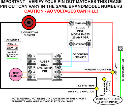
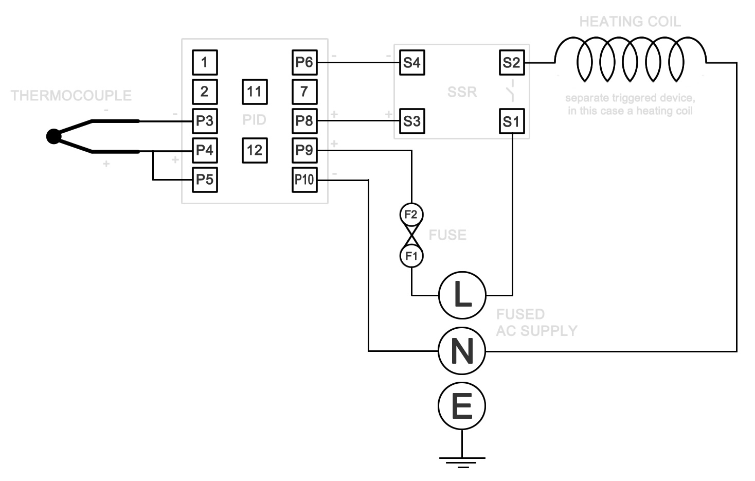
If Negative temperature Coefficient NTC type thermistor is used then the resistance of the thermistor decreases after heating. 7 8 and RTD3 to terminal No. The PID has 12 numbered screw terminals and the silver label diagram shows where the SSR and the Thermocouple TC are wired to these.
Heatmiser UH8-N The Heatmiser UH8-N is designed to be used in conjunction with our 12v thermostats. Performance of an electrical heat tracing system. Some PID controllers can switch high power heaters directly others will need solid state relays.
This is done to verify the accuracy of the signal and the gauge. You can try it at home. Staged wiring digram - Heat Pump with Auxiliary Dehumidi.
During the initial heat-up phase of the sensor the output will toggle 10AFR 20AFR. Newer Post Older Post Home. This Heat Sensor is not only simple but also effective.
Wiring diagrams - Johnson Controls - LIT-12013163 - TEC3631-1x-xxx - Wireless Thermostat - TEC3000 Series Networked and Wireless Single- or Two-Stage Economizer Thermostat Controllers. In the instruction manual for your PID and possibly on a sticker on the case will be a wiring diagram like the one above. This temperature property of transistor is used here to use it as a heat sensor.
BC548 is an NPN transistor TO-92 type. As the temperature of PN junction increase transistor starts conducting to some extent. Uses PID algorithm to control probe temperature.
Gaggia Classic Wiring Diagrams Posted on December 13 2013 by admin When you switch on the power using the main switch on the front panel power is provided to the front panel neon which lights provided the thermal fuse in the neutral wire is intact. Staged wiring diagram - Rooftop Unit with Auxiliary Dehumidifier Note. Heat Probe Pid Wiring Diagram - 10072010 How I wired a PID to control temperature If this is your first visit be sure to check out the FAQ by clicking the link above.
The heat tracing system compensates for the remaining losses. However its not instantly clear what to do with the SSR and how and where to power everything. Schematic Reheat Valve or SCR.
Read Or Download The Diagram Pictures Probe Pid For FREE Wiring Diagram at CROWDFUNDING-EQUITYDEMOAGRIYACOM. Therefore problems with thermal. To switch back to 0-5V output repeat the same precedure.
Since the wiring will depend on the type of thermocouple PID controller heating element you use. Heat Probe Pid Wiring Diagram Wiring Diagram Schematics Temperature Wiring Diagram Wiring Diagram Rex Controller Wiring Diagram C10 Wiring Diagram Stc 1000 Temperature Controller Wiring Diagram Book Of Perfect Stc Share this post. We can use other alternatives like 2N2222 BC168 BC238 BC183 etc.
Representative becomes the source for certified prints wiring diagrams complete submittal information. To do this connect the wire to ground and turn on the controller for 3 seconds. When the temperature exceeds a.
If you know how to translate it wiring everything up is quite simple. VAV Damper and Floating Reheat Wiring. Maybe you have already created a fermentation temperature controller but now you want it to be PID controlled and have the data displayed on your.
Connect PT100 between terminal no. 1 FOR THERMOCOUPLE TCTC-6 7 8 910 THERMOCOUPLE - 1 FOR TWO WIRE PT-100. A specific wiring diagram is furnished for every.
Using our wiring centres in your application means that the actuator boiler and pump connections are wired from a single point. See Figure 6 for auxiliary contact wiring Figure 4. Because the characteristics are almost the same for these types of transistors.
Connect RTD1 RTD2 of A B RTD 6 7 8 910 2 FOR RTD PT-100 2 WIRE 3 WIRE 3 wire PT100 to terminal no.
 How To Build A Temperature Controller American Homebrewers Association
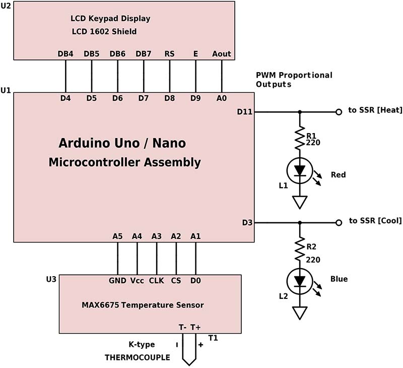 Arduino Pid Temperature Control Nuts Volts Magazine
 Pid Inkbird Itc 100vh Wiring Usage Overview
 2 Element 2 Pump Single Pid Wiring Help Home Brew Forums Home Brewing Home Brewery Beer Crafts


